Installing Cornering Lamps on your 1994 - 1996 Chevy Caprice and other B bodys.
Hello and welcome, this article is written to help you get an idea of what it would take to add cornering lamps to your Caprice. I happen to own a low option 1994 wagon that includes not having the T87 RPO code for cornering lamps. For those linking directly to this article, the work here is being done on a 1994 Chevy Caprice Station Wagon. This article should work for all 1994 to 1996 B body cars.
The reason for writing this article goes back to my mother's 1992 Chevy Caprice Sedan...she had cornering lamps...so when I bought my wagon, I figured I'd have the same...WRONG...well, thanks to the kind folks at the Impala SS Forum (shout out to the Wagon guys!), they provided some insight into the project and without them, this upgrade would not have been possible. FYI, this procedure DOES NOT WORK on pre-1994 cars.
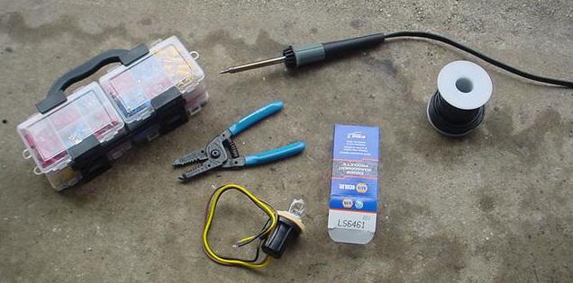
Lets start with the players:
To start this project, you're going to need some basic skills in hardware and wiring. All my connections are solder connections, but you could do this project using crimped fitings.
First thing first, you'll need the lamp sockets and lamps. I got mine at Hampden Auto Parts, which is a NAPA dealer. You'll need LS6461...well, actually you'll need two of them....and the bulbs, which are 2057. This is a duel filament bulb, but we'll only use the bright side. I also used 18 gauge wire, heat shrink wrap, electrical tape, solder and a soldering gun, a couple zip ties, and of course a Caprice without cornering lamps. You'll also need a drill and cutting tools, which we'll get to in the first phase...cutting the holes:
Pre-check to make sure your lights are working before you begin and run into trouble later...no point in chasing down a dead blinker when they never worked in the first place...also, disconnect the battery for safety when working on any part of the electrical system.
Phase 1 - Side Marker Lenses
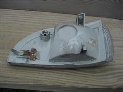
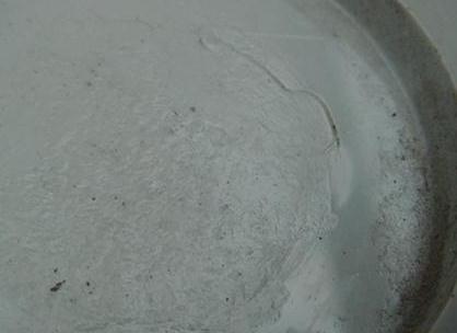
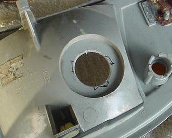
We'll first prepare the side marker lenses for the sockets and do the wiring in phase 2. Below is a picture of the back of the side marker light. Removing this item from the car is easy. There is a phillips head screw right next to the headlight, remove it and just pull the lens forward. Disconnect the side marker light and it's free. The second picture is a close up of area we're working with, as you can tell, originally the design had the hole, but in the process to remove this option from cars, they filled it in.
But, that doesn't matter now as we'll be making our own hole. I would mention how large of a hole, but you really need to just make sure it is the perfect size for your socket. I first started with a pilot hole, which is 1/8" dead center in the socket area. Now, I don't have a drill this large, and that's a problem. What I do have is an Air Rotary tool and a bunch of grinding stones, one of them is cone shaped. To use this, I drilled a slightly larger hole with the biggest drill bit I have to make it bit bigger (not shown) and finally I use the air powered stone to essentially melt the hole to the size I needed. This couldn't have worked better as the size of my stone was the same size as the hole I needed. If you don't have a large drill, you can try drilling lots of little holes in a circle and punch out the center, or if you have a dremel tool, use a variety of cutting bits to achieve your goal. This plastic is hard and thick enough to making using a knife nearly impossible.
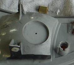
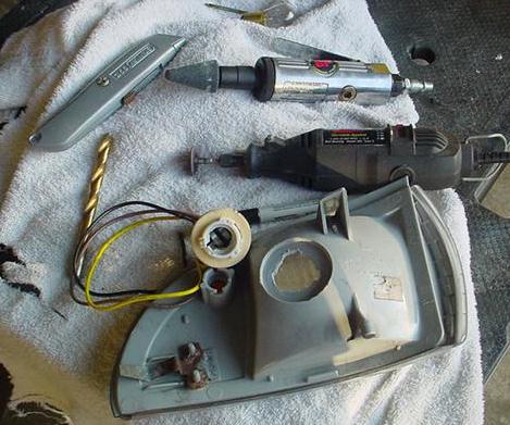
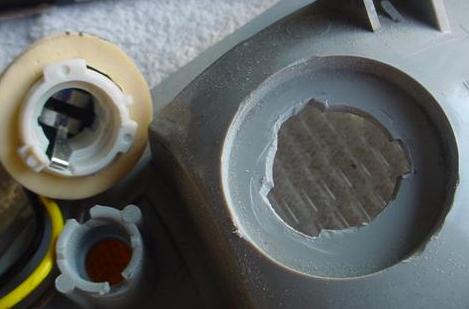
A note about using a grinding stone...this actually melts the plastic..it's best to proceed slowly and to clear out the melt plastic a couple of times...this prevents the bit from getting stuck. Now, as seen above, you'll need to make at least 3 indents in your whole to accommodate the locking mechanism of the socket...this allows you to insert and then turn the socket so it doesn't fall out. I did this with a dremel rotary tool using a basic cutting blade. A hint, the cutting blade will also melt the plastic, so take your time and use a low RPM...also make sure the disk is spinning UP on the cutting edge...that allows the plastic to build up on the outside of the lens and thus easier to remove. Below are the tools I used and also the finished hole.
Phase 1 is complete...you can now install the bulbs, lock the sockets in the lenses, and pull the wires through the hole behind the socket in the body and install the side marker lenses. I used electrical tape to keep the wires of the socket together.
Phase 2 - Electrical Wiring
This is actually the fun part and easiest part for me as I'm a hobby electronics guy. We'll start off with the Factory Service Manual wire drawing for the cornering lamps. We'll connect this to the real world wiring in a few pictures.

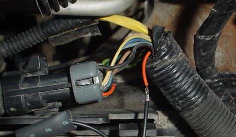
All we need to know from this picture is that the left cornering lamp is an ORANGE WIRE and the right is a BLACK WIRE. Also note that these wires do nothing else besides power the cornering lamps. Our wiring goes through Connector C100, which is noted in the below picture. LOW and BEHOLD!...our black and orange wires enter the connector, but they don't leave...there is nothing on the other side. Now, if you're good with connectors, I'm sure you could fix it and run the wires like OEM, but I'm in a hurry, so I just cut the wires before they enter the connection.
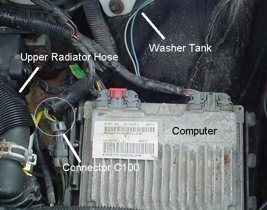
Some help with the above picture. To get here, I had to remove the air cleaner assembly...all of it, including the base. This shows the computer. For reference, I'm standing in front the of the driver's side headlight and shooting down. In Connector C100, our two wires are on top...you don't need to remove the air box to see them, but it makes it easier to work on them. I have circled the area where our two wires enter the connector.
Below is a an overhead view of the connector with me over the fender of the car. As you can see, I've cut the orange wire and soldered it to a black section wire...I think the wire I used was 18 gauge, the wire on the sockets looks to be almost 16 gauge, and the orange factory wire is almost 20 gauge...very small stuff. I pretty much just solder the two wires in-line...not the best, but it's fast and good looking when done. I soldered this to my YELLOW (bright) wire of my socket...the brown wire is the dim and I just cut it back. Some heat shrink and we're done here. NEXT!
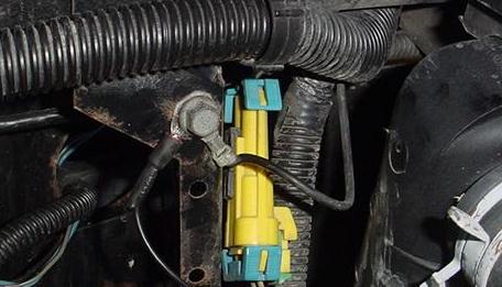
We need a ground. Easiest ground I could find was right next to the radiator. Not sure what it's used for, but it shouldn't hurt me adding to it. I used a crimp type fitting here and soldered the wire to it. To the right is the upper radiator hose. While I was here, I cleaned the ground it to make sure it made good metal contact. There is an identical one on the other side of the radiator that is good for the right side. The yellow airbag connector is a good hint as to where this left side ground is located.
Ok...left side done...do the same for the right side...connect the upper black wire of C100 to the YELLOW of the socket, the ground of the socket to ground...and that's it. I ran my right side power wire with all the other wires in front of the radiator and used black zip ties to make sure it didn't move. I pulled my right side cornering lamp wires above the battery and made all my connections there, then stuffed them all in front of the battery. I'll clean that up next time I remove the battery.
Reconnect your intake air ducting, remove all your tools, turn the car on (not started), TURN ON YOUR HEADLIGHTS as they need to be on for the cornering lamps to work...turn on a blinker and volia! Cornering Lamps! And you did it yourself! Enjoy my lame movie below.
If you have any questions or comments, please feel free to contact me at TheReflex1@aol.com. I 'd appreciate a note if you used this article, it helps me to write other articles. Original created 1/21/2005. Thanks for reading.